Continuous Beam Crack [32|64bit] 2022 [New]
- spacimesadlin
- May 11, 2022
- 4 min read

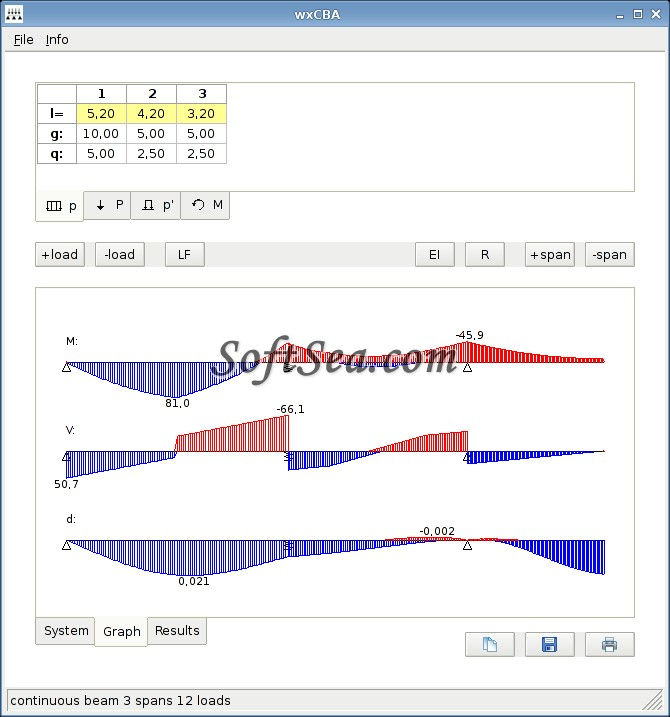
Continuous Beam (LifeTime) Activation Code Download [Mac/Win] [2022] Sketch the beam using the following parameters: The beam can be subjected to shear force in any point along the length. A concentrated force is applied to the right end and bending moment is distributed to the beam. the beam has a uniform cross-section. I have included a free version of the Excel file that you can use. When you have downloaded the file, save it on your computer and open it. When you are done, you can print the file or save it as an Excel file. The beam section can be modified using the following options: For the entire beam. A Section with two nodes, with the right node at the right end of the beam. A Section with two nodes, with the right node at the center of the beam. A Section with three nodes, with the center node at the center of the beam. A Section with two nodes, with the center node at the center of the beam. A Section with four nodes, with the center node at the center of the beam. You can modify the values of all the parameters of the beam. By clicking on the Excel file you can see and modify all the parameters. There is a picture of the section that can be used as a reference. The beam can be stretched or compressed along the length. It can be subjected to any load or forces. Beam Curvature: Since the cross-section of the beam is rectangular, and the lengths are in meters, if the beam is subjected to bending moment and shear force along its length, it will be deformed according to the law of curvature. The arc length A from one end of the beam to the other is 12.5m. In this case, if we apply a load of F=700N at one end, the maximum deflection will be 10.2mm. I have included a picture of the beam section. If you have downloaded the Excel file, you can use it to know the maximum deflection. The section of the beam can be curved or flat. If you use a section curved, the maximum deflection will be zero. If you use a section flat, the maximum deflection will be 33.6mm. You can also analyze the beam section using this function. The result is a table of bending moment and shear force for the different Continuous Beam X64 8e68912320 Continuous Beam Crack+ Product Key Free Download This Excel macro helps in analyzing bending moments and shear forces of beam types (I, G, H) with continuous bending. The macro displays the results in three diagrams: * Sums of bending moments for each section * Sum of shear forces for each section * Sum of the maximum and minimum values of the bending moments for each section Each graph can be activated by clicking a section of the beam. The reason for this is that the over-load distribution of a reinforced concrete column is mainly determined by the reinforcement, and that any form of normal distribution of force will have a much greater effect on the reinforcement than the other elements of the column. In the case of a reinforcement that is a slender bar (as opposed to a jacket), the average reinforcement is subjected to much more loading than it is for the jacket reinforcement. An increase of loading will cause local stresses in the reinforcement, but only in the case of reinforcement that is slender. The modal representation of the column represents a triangular distribution of stress forces, with a total stress of zero at all three vertices. The length of the base of the triangle depends on the distribution of reinforcement in the column. In the case of reinforcement that is slender, the length of the base of the triangle will be very small, and its position will be distant from the reinforcement. However, in the case of reinforcement that is embedded, the length of the base will be relatively large, and the position of the reinforcement will be closer to the reinforcement. The modal representation of the column also shows that the concrete will react to the reinforcement. In the case of reinforcement that is slender, the maximum local stress in the concrete will be close to the reinforcement. In the case of reinforcement that is embedded, the maximum local stress in the concrete will be far from the reinforcement. The Modal Representation of the Column 1) Construction of the Constructional Elements The element can be constructed manually or using the module Construction. The modal representation of the column can be constructed using the following steps: 1.1) Using the module Table, enter the data of the modal representation of the reinforcement, including the data of the concrete cross section, its modulus of elasticity, and the distribution of reinforcement. 1.2) Use the module Construction to build the modal representation of the column. 1.3) Use the module Testing, What's New in the? System Requirements: Software Requirements: Performance Requirements: Minimum Pixels Per Second (PPS): 4.0 – 8.0 Maximum Pixels Per Second (PPS): 50.0 – 80.0 Minimum Frames Per Second (FPS): 30.0 – 60.0 Maximum Frames Per Second (FPS): 120.0 – 160.0 Postprocessing: Minimum Post Processing AA: 5x Maximum Post Processing AA: 25x Minimum Post Processing Soft Shadows:
Related links:
![ColorPic Crack Activation Key Free [Win/Mac] (2022)](https://static.wixstatic.com/media/69caca_10a361cf56e6431bbca279621c4985d1~mv2.png/v1/fill/w_284,h_550,al_c,q_85,enc_avif,quality_auto/69caca_10a361cf56e6431bbca279621c4985d1~mv2.png)


Comments